The Essential Guide on PCB Fabrication Techniques!


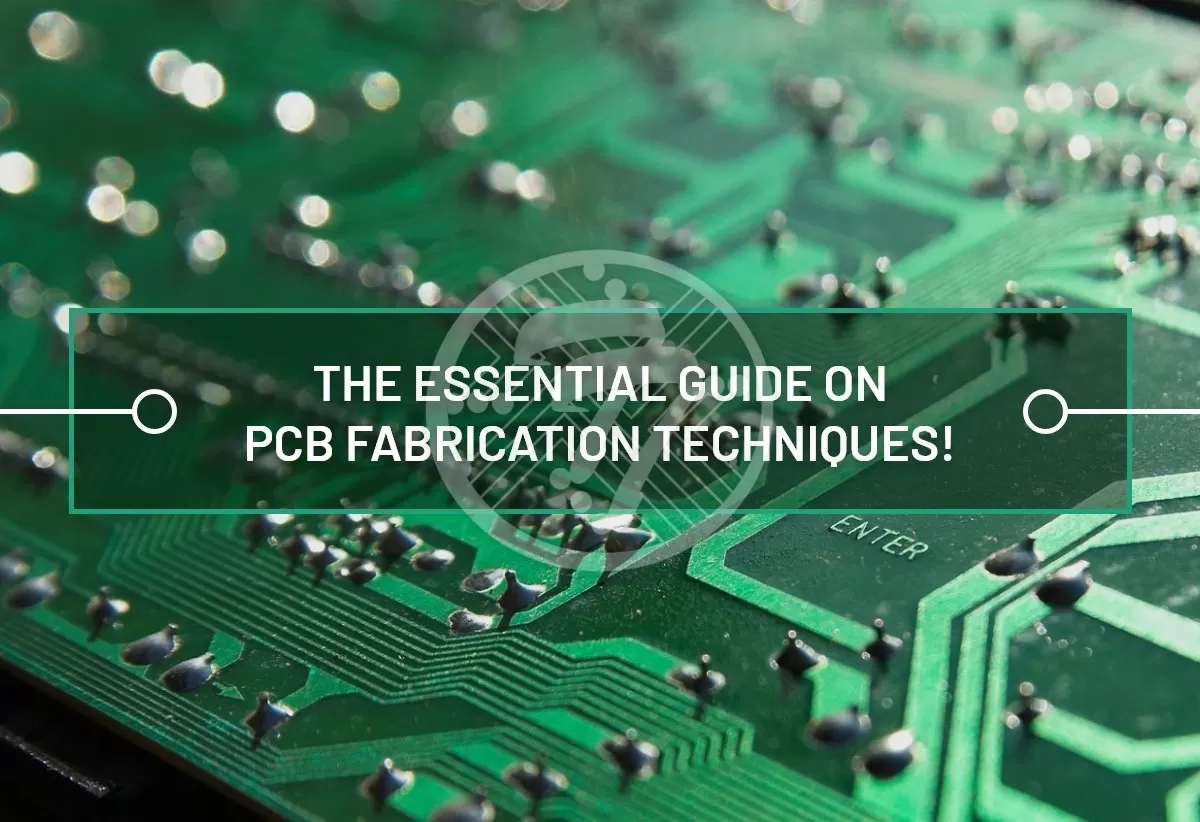
Before delving into the PCB Fabrication techniques, it will be worthwhile to understand what exactly PCB Fabrication means. Simply put, PCB Fabrication refers to the process that transforms a PCB board design into a physical structure. This structure, of course, is built on the exact specifications provided in the design package. If you are a designer, an overview of PCB Fabrication Techniques can go a long way in helping you design the PCB in a manner that manufacturability is not compromised.
Here are the techniques involved in the process of PCB Fabrication:
Imaging
This is the stage where your digital PCB design translates into the physical board. Here are the steps involved in the process:
- The image of the PCB layout and design
- The board is coated with liquid photoresist.
- While the exposed areas of the photoresist harden the remaining is removed.
PCB Etching
This process essentially involves removing the excess metal from the PCB by way of an industrial solvent. Popular etching chemicals include:
- Ferric Chloride
- Cupric Chloride
- Alkaline Ammonia
- Ammonium persulfate
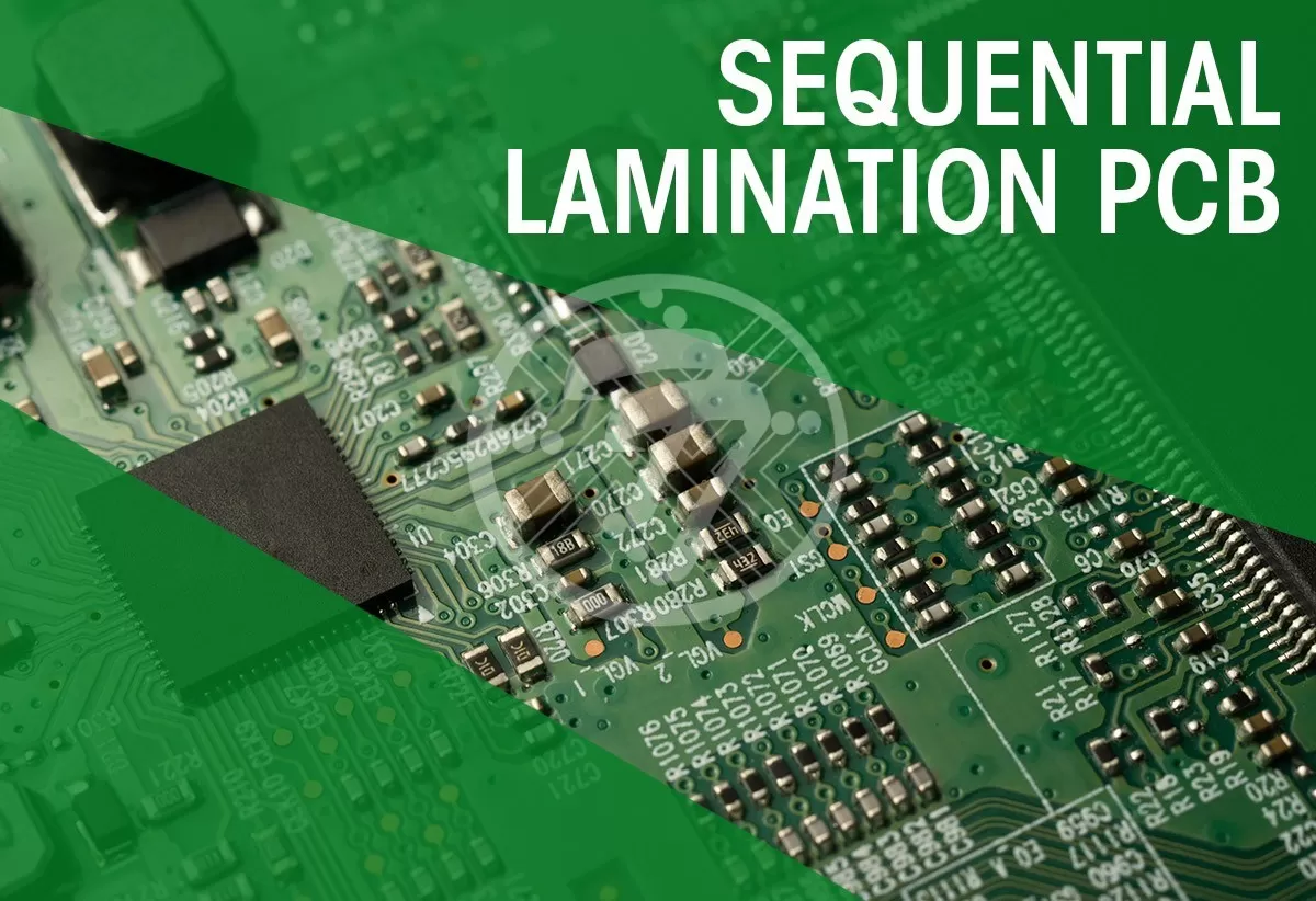
PCB Lamination
More often than not, a PCB comprises of multiple layers of copper which are interspersed with non-conductive substrate. In the process of PCB lamination, heat and pressure are applied to the various layers.
Machining
Machining takes place a number of times in the PCB manufacturing process, largely at the following stages:
- Through-holes and vias: Stacking multiple boards together, securing them in place and drilling through holes, can go a long way in saving time and money. Ideally the non-plated holes are drilled after the photoresist is applied.
- Panelization: The process of panelization ensures that multiple boards can be fabricated and tested in one go. V Scores or breakaways can facilitate removal of the board once the process of manufacturing gets over.
When it comes to manufacturability of the boards there are a number of factors that need to be kept into account. Some of these include:
- Thickness of the PCB
- Choice of material
- Type of drilling
Plating
Depending on the environment in which the PCB has to function, there can be a wide variety of plating that can be done. Some of the common plating techniques include:
- Electrolytic Plating: This kind of plating works well for high volume projects. A concentrated solution of the plating metal is used to dip the boards. A process of electrolysis follows that plates the exposed metal surfaces.
- Electroless Plating: As the name suggests, this does not involve the use of electric current. Instead self-reducing agents are used. The big advantage that this offers is that the coating turns out to be uniform and anomalies are minimized
- Dry Plating: Also referred to as Plasma Plating, this works well for fine line circuit plating. This involves the use of an inert gas. The metal particles from a charged target is removed and re-deposited on the target under a vacuum.
The importance of understanding the PCB Fabrication Process
It is imperative to understand the PCB Fabrication process to be able to make a tangible difference to the following areas:
PCB Manufacturability
A comprehensive understanding of the above processes can go a long way for PCB designers as minimum manufacturability issues are faced. The designers are also sensitized to the impact that aspects such as:
- Line width
- Spacing
- Number of holes etc., on the cost of the PCB.
The added advantage is that designing the board with these aspects in mind leads to ensuring that there are no costly errors at a later date which call for resigns and delay your project. In a milieu where quick go-to-market is a major source of competitive advantage, these delays can prove to be quite detrimental.
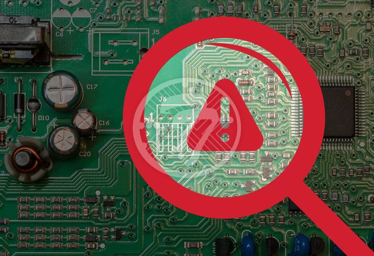
Reliability & Yield Rate
Inaccurate fabrication of boards can have a major impact on the yield rate of the board, so you may land up with many unusable boards. Also for your board to meet the classification standards it needs to meet some specified levels of reliability. If the board does not meet the classification standards, it could result in premature board failure.
Clearly then, the design choices made, have a far-reaching impact on all the subsequent stages of the PCB. Incorporating knowledge of PCB Fabrication at the design stage, can go a long way in improving the manufacturability and hence the efficiency of the PCB.
Technotronix can adopt advanced methods of PCB fabrication, which can give you the finest PCB fabrication services in the world. The PCB fab services from our experts will take it to the next level by accepting every type of latest technologies. They understand every needs of the clients and offer smart & multi-layer PCBs.